Home
|
BBG-SSCS
Synchro Signal Conversion
System
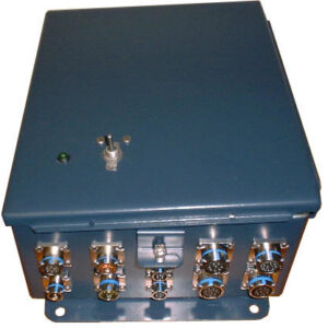
Introduction
|
 |
 |
The BBG-SSCS provides
four channels of synchro/resolver to high power
synchro conversion. Each channel is fault
protected against over current and over temperature
faults. In addition, the SSCS provides power supply
status, BIT status and internal kick circuitry for
added control and protection. An onboard
microcontroller configures the cards from power up
or reset and provides all signals and control to
read the synchro input information and output the
125VA synchro/resolver information. Health
monitoring of each 1X/36X channel for over-current,
over-temperature and loss of reference is provided
via visual display indicators. Synchro data formats,
power outputs, synchro and resolver voltages and
frequencies are factory configured to user
requirements. |
Card Layout
|
|

The SSCS operates on 115 Volt, 60 Hz AC power to convert synchro
inputs into high power synchro outputs.
The SSCS accepts two channels of 60 Hz synchro data and two
channels of 400 Hz synchro data.
Specifications
|
|
Parameter |
Value |
Units |
Power Supply |
115 |
Volts AC |
60 |
Hertz |
6.3 |
Amps |
Temperature Range |
|
|
Operating |
-25
to +85 |
°C |
Storage |
-65 to +125 |
°C |
Inputs |
|
|
Reference Input |
115 |
Volts AC |
60/400 |
Hertz |
Synchro (Channel 1 1X , 36X) |
90 |
Volts |
60/400 |
Hertz |
Synchro (Channel 2 1X , 36X) |
90 |
Volts |
60/400 |
Hertz |
Outputs |
|
|
Synchro (Channel 1
1X , 36X) |
90 |
Volts |
400 |
Hertz |
125 |
VA (Peak) |
30 |
VA (Continuous) |
Synchro (Channel 2
1X , 36X) |
90 |
Volts |
60 |
Hertz |
125 |
VA (Peak) |
30 |
VA (Continuous) |
Accuracy |
+/-4 |
arc minutes |
Dimensions |
30.0 x
12.0 x 12.0 |
in. |
76.2
x 30.48 x 30.48 |
cm. |
BBG-SSCS
Overview
|
The SSCS provides four channels of
synchro/resolver to high power synchro conversion.
Each channel is fault protected against over current and
over temperature faults. In addition, the SSCS
provides power supply status, BIT status and internal
kick circuitry for added control and protection. An
onboard microcontroller configures the cards from power
up or reset and provides all signals and control to read
the synchro input information and output the 125VA
synchro/resolver information. Health monitoring of each
1X/36X channel for over-current, over-temperature and
loss of reference is provided via visual display
indicators. Synchro data formats, power outputs, synchro
and resolver voltages and frequencies are factory
configured to user requirements. |
|
Data Sheet
|
If you need more
information, click on the link below for the data sheet.
For any questions or to request a quote, click on the
"Request Quote" Icon or the "Contact Us"
button on the
side bar.
Data
Sheet |
|

|