Home
|
BBG-DSC2
Analog/Serial to 2-Channel
Synchro/Resolver
"Smart" Converter Card
Introduction
|
 |
 |
- IBM PC Compatible
- Analog/Serial Input
- Analog/Serial and Two-Speed Synchro/Resolver
Outputs
- NMEA-0183 Compatible RS-232, RS-422,
RS-423, RS-485, MIL-STD-188C Protocols
- Dual Port Interface to PCbus
- Stand-alone Mode with Additional
Power Supply
- Custom Implementations Available Upon
Request
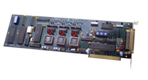
The BBG-DSC2 is a PCbus compatible card
which interfaces to any slot of an IBM PC or clone. This
board receives angular information from an analog or serial
data input and produces three outputs: a two speed synchro
or resolver signal, two analog channels, and/or a serial
data channel.
The synchro format output is a standard 5
wire (S1,S2,S3,RL, and RH) at 90V LL or 11.8V LL. Resolver
output is a standard 6 wire (Sin, Sin Return, Cos, Cos
Return, RH, and RL) at 6.8Vrms. Standard reference inputs of
60 Hz and 400 Hz are supported with custom voltages and
frequencies available upon request.
The serial data output uses the NMEA 0183
message structures and supports RS-232, RS-422, RS-423,
RS-485, and MIL-STD-188C protocols. The analog I/O
interfaces to dc signals over the range of -5 to +5 volts.
The BBG-DSC2 is a "SMART" interface due to
the onboard processor which communicates with the PCbus
through shared memory, thus, requiring minimum PC processor
time. Angular information is available to the PCbus via
shared memory.
In situations not requiring a PC
interface, the BBG-DSC2 operates in a "STAND-ALONE" mode.
With the addition of an external +5 volt power supply, the
onboard processor converts the serial inputs into synchro/resolver
and serial data formats without the requirement of a PCbus.
Reference inputs, serial inputs, synchro/resolver
outputs, and serial outputs are available on a 50 pin male
(DB50P) connector.
|
Card Layout
|
|

Technical Specification
|
|
BBG-DSC2
Overview
|
The BBG-DSC2 is a full-size
IBM PC card which interfaces between analog, serial, synchro,
and/or resolver signals. Two channels of analog information
(-5 to +5 voltage range) and/or one channel of serial
information representing speed or angular position can be
received and processed by the onboard microcontroller. This
data, formatted as a binary angle measurement (BAM) number
as shown in Table 2, is passed through dual port memory to
the PCbus on demand from the host computer.
The processed angular information is,
also, available in three different data formats on a 50 pin
"D" connector. A NMEA-0183 serial data format updated at a
rate of once per second is transmitted over both RS-232 and
RS-422 interfaces. Two channels of analog information (-5
volt to +5 voltage range) is transmitted continuously. Two
factory configurable synchro or resolver outputs
representing speed and/or angular position is output
continuously at a user defined voltage and frequency. The
synchro/resolver outputs can be two independent channels or
one dual speed channel (1X, 36X).
The BBG-DSC2 can, also, be used without a
computer in a stand alone mode. During power up or reset, an
onboard microcontroller reads the configuration switch and
configures the card to provide all signals and control
necessary for full interface operation.
When used in a computer configuration,
switches provide for bus address selection and interrupts
IRQ2 thru IRQ7 are jumper selectable. Baud rates are switch
selectable and can be programmed via the PC bus. Selectable
baud rates include: 1200, 2400, 4800, 9600, and 19,200 bits
per second. Default data output is 9600, 8 bits, no parity,
and one stop bit (9600, 8, N, 1). Table 3 (on the data
sheet) defines the switch
position for the available baud rates. |
Data Sheet
|
If you need more
information, click on the link below for the data sheet.
For any questions or to request a quote, click on the
"Request Quote" Icon or the "Contact Us"
button on the
side bar.
Data
Sheet |
|

|